We are temporarily unavailable because of our losses in the massive Black Forest Forest Fire.
 |
 |
 |
 |
 |
 |
| Order µSmartDigi APRS Digipeater
or D-Gate NOW! The µSmartDigi and TNC-X can be ordered by selecting the links below. These use John Hansen's PayPal Shopping Cart for your convenience. You can also obtain more information or order the TNC-X directly from tnc-x.com. John will ship you the TNC-X products and I will ship you the µSmartDigi and integrated TNC-X. Under certain conditions I may ship your µSmartDigi to John for incorporation with his shipment to you.
|
| Special
Note
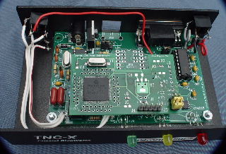
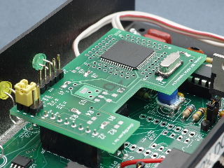
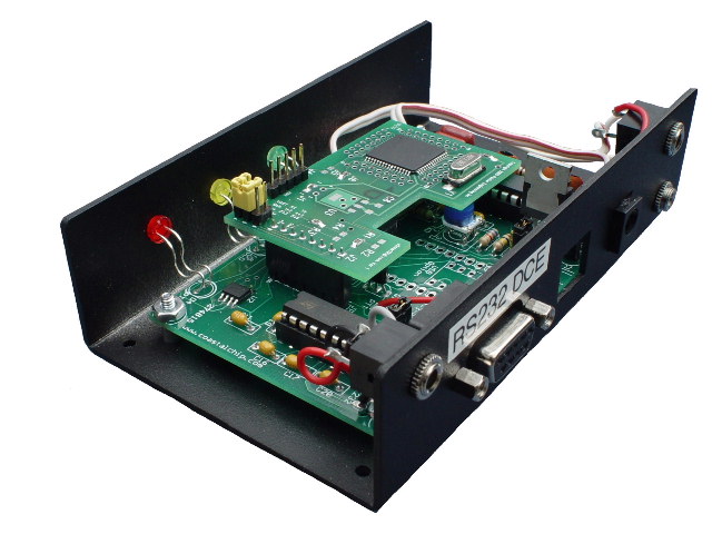
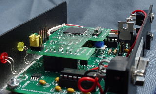
for both Digi and D-Gate When powering the µSmartDigi-TNC-X with input voltages above 9 volts DC you will need to either add a heat sink to the 7805 voltage regulator or relocate the regulator to use the TNC-X metal enclosure as a heat sink. You may use the PCB-mounted 7805 without a heat sink if you are using an input from 7.5v to 9v DC. This is the preferred method since the TNC-X PCB can be serviced without removing or unbolting the regulator. The PCB hold-down screws and DB9 screws can be removed and the PCB can be rotated upward. Here are the instructions for mounting the 7805 to the metal enclosure.
Photos for the mounting of the regulator are HERE. |
| Features |
Benefits |
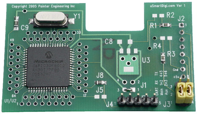
| Tiny Size- It plugs into the
TNC-X and fits within its case. |
Self contained in TNC-X.
Very Portable. Easily fits
in a vehicle. |
| Low Power Consumption
(typical 130 mA, maximum 220mA) |
Battery Operation. |
| Performs Duplicate Packet
checking based on the Source, Source SSID, Destination and Info Fields
Only! |
Correctly eliminates repeating
of Duplicate Packets after filtering. |
| User Configurable Rules for
Packet Filtering with a rich set of parameters. |
Precisely control Repeater
Traffic, especially for emergency service operation. |
| User-Configurable settings for limiting the WIDE and WIDEn counts in the VIA Path. | Provides Repeater Operators
better control over malformed paths. |
| GPS RS-232 Serial Interface for
connecting a GPS unit. |
Provides automatic location or
supports mobile operation. |
| Configure Configuration and
Rules once with a PC or Laptop. Saved in EEPROM. |
Completely computer- and
hands-free operation after configuring. |
| Configuration Parameters can be changed using Hyperterminal (or similar) directly connected to the µSmartDigi | Fast changes and no need for the µSmartDigi PC Configuration Program. |
| Flash Program Updates using a PC
or Laptop computer. |
Easy to update firmware without
requiring a programmer. |
| Support planned for No Source
Routing (NSR)
[not fully implemented in Version 2] |
You can use conventional routing
or NSR. |
| Windows 32-bit Console program
is used to download the Configuration Parameters, Rules and Firmware
updates. |
Common platform. |
| Parameter |
Arguments |
Description |
Ver |
| call |
CALL |
Sets the Call Sign | |
| ssid | SSID | Sets the SSID with Decimal, Octal or Hex number | |
| position | Lat Lon | Sets the Base Latitude and Longitude (alias base) | |
| base |
Lat Lon | same as position |
|
| lat |
Lat |
Sets the Base Latitude | |
| lon |
Lon |
Sets the Base Longitude | |
| altitude |
nF | nM |
Specify station's altitude in feet (F) or meters (M) [Use NO decimal points!] | |
| digipath | string | Comma or space separated (no tab) Digi Path | |
| uitrace1 |
Toggles ON and OFF
UITrace
digipath debugging mode. Default is ON. |
||
| beacon | seconds |
Sets the beacon period in
seconds, 0 for OFF, range [10..65535] |
|
| icon | xx |
2 characters representing the
Symbol Table ID or Overlay and Symbol Code |
|
| bcomment | string |
Sets the beacon comment string4 |
2.83a |
| havegps1 |
y | n |
Sets existence of a GPS |
|
| log |
y | n |
Enables | Disables Logging to
the
Monitor/GPS Port |
|
| nonaprs1 | y | n |
Enables | Disables repeating of
packets without valid position info |
|
| dropmangled | y | n | Enables | Disables dropping mangled packets | |
| haltonerr | y | n | Enables | Disables halting on
error [for testing only] |
|
| host | [baud] | Sets optional Host baud | |
| tnc |
[baud] |
Sets optional TNC baud |
|
| gps1 | [baud] | Sets optional GPS baud |
|
| dstar2 | [baud] | Sets optional D-STAR baud | |
| nsr3 | y | n | Enables | Disables No Source Routing | |
| relaydrop1 | y | n | Enables | Disables dropping anything with RELAY in Digi1 path | |
| widemax1 |
N |
Sets the maximum wideN in the
remaining path |
|
| widetotal1 |
N |
Sets the maximum total wide for
the remaining path |
|
| ratelimcall | seconds |
Sets the Rate Limit Window in
seconds for all Call Signs. 0 disables feature. |
2.7 |
| dupewin |
seconds |
Sets the Duplicate Check Window
Time in seconds |
|
| deletepath1 | MI MS DI | Deletes digipath component matching the arguments. MI is the Match Index (0, *, 1-8). MS is the Match String (*, xxx*, xxx-SSID). DI is the Delete Index (0, *, 1-8). | 2.8 |
| substitutepath1 | MI MS SI DL1,DL2... | Substitutes the DL Digi List matching the arguments. MI is the Match Index (0, *, 1-8). MS is the Match String (*, xxx*, xxx-SSID). SI is the Substitution Index (0, *, 1-8) where the substitution takes place. DL is a comma separated list of digis with optional * | 2.8 |
| controlcall1 | CALL-SSID | Source call allowed to perform the OTA run control | 2.8 |
| fixvalid2 | y | n |
Enables | Disables
requiring the GPS fix to be valid |
|
| deditpath |
Displays the Substitution |
2.8 |
| Command |
Arguments |
Description |
Ver |
| help |
Displays
the Commands (alias ?) |
||
| ? |
same as help |
||
| angles |
Displays
the Angles format used
for Lat, Lon and Rules |
||
| baud |
baud |
Changes the baud rates on host and µSmartDigi once connected | |
| configure |
file_name |
Reads a
Configuration File named
file_name |
|
| rules |
file_name |
Reads a Rule File named file_name | |
| dconfigure |
Displays
the current
Configuration |
||
| drules |
Displays the current Rules | ||
| connect |
com_port
[baud] |
Connects to
the µSmartDigi
on com_port at optional baud to enable a download |
|
| disconnect |
Disconnects from the µSmartDigi | ||
| download |
Downloads
the Configuration and
Rules to the µSmartDigi
(requires connection) |
||
| firmware |
com_port
file_name |
Updates µSmartDigi
firmware on com_port from HEX file file_name |
|
| serialtest |
iterations |
Performs a write and read loop test between the serial port and µSmartDigi | 2.7 |
| . |
[Period] Repeat the last
command. Normal DOS/WIN edit commands apply. |
||
| exit |
Exits the
program |
||
| quit |
same as exit |
||
| x |
same as exit |
| Command |
Arguments |
Description |
Ver |
| version |
Displays the firmware version |
2.7 |
|
| help |
Displays the Commands (alias ?) |
||
| ? |
same as help |
||
| monitor |
Enables TNC and enters Monitor
mode |
||
| debug |
Toggles ON and OFF decoded
display of incoming packet (VOLATILE) |
||
| log |
y | n |
Enables | Disables Logging to the Monitor/GPS Port | |
| havegps1 |
y | n |
Sets existence of a GPS. Monitor/GPS Port switches to baud set by command gps | |
| tnc |
[baud] |
Sets optional baud, enables TNC
and enters Monitor mode |
|
| control-c |
Breaks out of Monitor mode and
returns to the command prompt |
||
| gps1 |
[baud] | Sets optional baud and enters
GPS mode |
|
| dstar2 | [baud] |
Sets optional baud and enters D-STAR mode | |
| host |
[baud] |
Sets optional Host baud |
|
| call |
CALL |
Sets the Call Sign |
|
| ssid |
SSID |
Sets the SSID with Decimal,
Octal or Hex number |
|
| digipath | string | Comma or space separated (no tab) Digi Path | |
| uitrace1 |
Toggles ON and OFF UITrace digipath debugging mode. Default is ON. | ||
| beacon | seconds | Sets the beacon period in seconds, 0 for OFF, range [10..65535] | |
| icon |
xx |
2 characters representing the Symbol Table ID or Overlay and Symbol Code | |
| bcomment | string |
Sets the beacon comment string | |
| implicit |
drop | pass |
Sets the Implicit Rule Action
(drop or pass) |
|
| widemax1 |
N |
Sets the maximum for any element
of the digipath |
|
| widetotal1 |
N |
Sets the maximum total of all
elements for the digipath |
|
| ratelimcall |
seconds |
Sets the Rate Limit Window in seconds for all Call Signs. 0 disables feature | 2.7 |
| dupewin |
seconds |
Sets the Duplicate Check Window Time in seconds | |
| deletepath1 | MI MS DI |
Deletes digipath component matching the arguments. MI is the Match Index (0, *, 1-8). MS is the Match String (*, xxx*, xxx-SSID). DI is the Delete Index (0, *, 1-8). | 2.8 |
| substitutepath1 | MI MS SI DL1,DL2... |
Substitutes the DL Digi List
matching the arguments. MI is the Match Index (0, *, 1-8). MS is the
Match String (*, xxx*, xxx-SSID). SI is the Substitution Index (0, *,
1-8) where the substitution takes place. DL is a comma separated list
of digis with optional * |
2.8 |
| deditpath1 | Displays the Substitution and
Delete digipath entries |
2.8 |
|
| rmeditpath1 | N |
Removes a Substitution or Delete
digipath entry in position N |
2.8 |
| run1 | Toggles the run mode On and Off |
2.8 |
|
| controlcall1 | CALL-SSID |
Source call allowed to perform
the OTA run control |
2.8 |
| nsr3 |
y | n |
Enables | Disables No Source
Routing |
|
| relaydrop1 |
y | n | Enables | Disables dropping anything with RELAY in Digi1 path | |
| nonaprs1 |
y | n |
Enables | Disables repeating of
packets without valid position info |
|
| dropmangled |
y | n |
Enables | Disables dropping
mangled packets |
|
| haltonerr |
y | n |
Enables | Disables halting on error [for testing only] | |
| fixvalid |
y | n |
Enables | Disables
requiring GPS fix to be valid |
|
| position |
Lat Lon |
Sets the Base Latitude and
Longitude (alias base) |
|
| base |
Lat Lon | same as position | |
| lat |
Lat |
Sets the Base Latitude |
|
| lon |
Lon |
Sets the Base Longitude |
|
| altitude |
nF | nM |
Specify station's altitude in
feet (F) or meters (M) [Use NO decimal points!] |
|
| dconfigure |
Displays the Configuration |
||
| drules |
Displays all the Rules |
||
| clearrules |
Temporarily clears the
Rules. EEPROM Rules are not affected. Restored by RESET |
||
| angles |
Displays the Angles format used
for Lat and Lon and Rules |
||
| boot |
Reboots the system (aliases
reboot, reset) |
||
| reboot |
same as boot |
||
| reset |
same as boot |
µSmartDigi
Angles and Lat-Lon Specification
The
µSmartDigi
uses a very flexible format to specify angles such as Latitude,
Longitude and actual angles found in the Rules file. This allows
users to enter these angles in a format that is easy and familiar while
not being restrictive. Here are some examples: -38:33:29.222,
38.33.379, 42d23.7m33.9c, W104D40.6m
A
complete description for the the Angles Specification is found in the
latter part of the Rules description found HERE
and can also be displayed from the µSmartDigi
Monitor mode using the angles
command.
µSmartDigi
comes with a 2-page Getting Started Guide. See the Versions
tables below for the latest edition.
µSmartDigi
Digi and D-Gate D-STAR Gateway Technical Stuff
[Under Construction]
Here are
some presentations on topics related to APRS...
| Title |
Date |
Event |
| Presentation µSmartDigi™ | Jun 2006 | Texas Ham-Com |
| Paper µSmartDigi™:
an APRS® Digipeater and D-Gate™ D-STAR
Gateway v5 |
Sep 2006 |
ARRL-TAPR Digital Communications Conference |
| Presentation µSmartDigi™ | Sep 2006 | ARRL-TAPR Digital Communications Conference |
| Presentation µSmartDigi™ Alabama D-STAR Project | Oct 2006 |
Huntsville D-STAR Training
Conference |
| Presentation µSmartDigi™ Use and Configuration | Jun 2007 |
Texas Ham-Com |
| Presentation µSmartDigi™
New Features |
Jun 2008 |
Texas Ham-Com |
| Presentation Intro to APRS® | May 2009 |
Colorado HamCon |
| Presentation APRS®, KISS & AX.25 Protocols | May 2009 | Colorado HamCon |
Cables
Instructions
for making serial cables for the µSmartDigi
can be found HERE. Cabling for the TNC-X to the
Radio can be found in the TNC-X manual included with your TNC-X and
also at Coastal ChipWorks http://www.tnc-x.com/documentation.htm.
A TNC-X Radio wiring diagram for the older stereo connector model is http://www.tnc-x.com/hookup.gif
and for the new DIN connector model is http://www.tnc-x.com/hookup2.gif.
But in either case use the µSmartDigi
serial
cabling instructions instead of the serial wiring in these images.
Software and Documentation
Downloads
µSmartDigi
PC Configuration software and Firmware can be downloaded by selecting
the appropriate link from the table below. Make certain you have
selected the correct PCB and Chip Versions! Due to the small size
of the PC Utility it is the actual executable program file. A general
rule is to use the latest versions for each of the Firmware, PC Utility
and Instructions.
µSmartDigi
APRS Digipeater Versions
Firmware
| Firmware Version | PCB Version |
Chip |
Comments |
| 2.1 Released 20 Jun 2006 | 1.0 |
dsPIC30F6012A | Initial Release; Requires PC
Utility 2.1 and higher |
| 2.2 Updated 17 Aug 2006 | 1.0 | dsPIC30F6012A | Added commands nonaprs and clearrules; Requires PC Utility 2.2 and higher |
| 2.3 Updated 10 Nov 2006 | 1.0 |
dsPIC30F6012A | Sync rev to PC Utility; Requires PC Utility 2.3 and higher |
| 2.3a Updated 30 Nov 2006 | 1.0 |
dsPIC30F6012A | Added Monitor Mode serial interrupt crtl-c; Requires PC Utility 2.3 and higher |
| 2.3b Updated 2 Jan 2007 | 1.0 |
dsPIC30F6012A | Expand dupe time window; Requires PC Utility 2.3 and higher |
| 2.4 Updated 18 Mar 2007 | 1.0 |
dsPIC30F6012A | Add APnnnU, Beaconing, Monitor commands, add SSn-n, change relaydrop; Requires PC Utility 2.4 and higher |
| 2.5 Updated 1 Jul
2007 |
1.0, 2.0 |
dsPIC30F6012A | Add Beacon Icon; Requires PC Utility 2.5 and higher |
| 2.52a Updated 24 Jul 2007 | 1.0, 2.0 | dsPIC30F6012A | Beacon uses MIC-E message format. Symbol # for Digi; Requires PC Utility 2.5 and higher |
| 2.6 Updated 26 Aug 2007 | 1.0, 2.0 | dsPIC30F6012A | uitrace, altitude, debug commands; don't repeat beacon; back space; digi counts; Requires PC Utility 2.6 and higher |
| 2.61 Updated 2 Nov 2007 | 1.0, 2.0 | dsPIC30F6012A | fix config & rule display, fix download; Requires PC Utility 2.61 and higher |
| 2.62a Updated 5 Nov 2007 | 1.0, 2.0 | dsPIC30F6012A | change default host serial speed to 19200 baud; Requires PC Utility 2.62 and higher |
| 2.7 Updated 2 Mar 2008 | 1.0, 2.0 | dsPIC30F6012A | add version, ratelimcall
commands; add serialtest; eliminate power cycle; Requires PC Utility
2.7 and higher. Use PCU 2.62 to upgrade. |
| 2.8 Updated 18
Jan 2009 |
1.0, 2.0 |
dsPIC30F6012A | Add run control, path editing and digipath rule; Requires PC Utility 2.8 and higher. |
| 2.81 Updated 10 Apr 2009 | 1.0, 2.0 |
dsPIC30F6012A | Fix Mic-E beacon encoding for lon < 10deg; Requires PC Utility 2.8 and higher. |
| 2.83 Updated 4 May 2009 | 1.0, 2.0 | dsPIC30F6012A | Fix dropmangled spelling, beacon lat-lon not updated after download w/o rest, expand debug output; Requires PC Utility 2.8 and higher. |
| 2.83b Updated 7 Sep 2009 | 1.0, 2.0 | dsPIC30F6012A | Fix angle spec; Requires PC Utility 2.83b and higher. |
| 2.83c Updated 24 Sep 2009 | 1.0, 2.0 | dsPIC30F6012A | Fix DST, SRC * rule; Requires PC Utility 2.83b and higher. |
| 2.83d Updated 24 Nov 2009 | 1.0, 2.0 |
dsPIC30F6012A | Make UITrace ON by default; Requires PC Utility 2.83d and higher. |
| 2.83e Updated 6 Nov 2010 | 1.0, 2.0 |
dsPIC30F6012A | Fixes MIC-E beacon Latitude for southern hemisphere; Requires PC Utility 2.83d and higher. |
| 2.83f Updated 4 May 2011 | 1.0, 2.0 | dsPIC30F6012A | Increase output buffer size and fix cpu trap for reset; Requires PC Utility 2.83d and higher. |
| PC Utility Version | PCB Version |
Chip |
Comments |
| 2.1 Released 20 Jun 2006 | 1.0 |
dsPIC30F6012A | Initial Release; Requires Firmware Version 2.1 and higher |
| 2.2 Updated July 2006 | 1.0 | dsPIC30F6012A | Added commands nonaprs and clearrules; Requires Firmware Version 2.2 and higher |
| 2.2b Updated 17Aug 2006 | 1.0 | dsPIC30F6012A | Requires Firmware Version 2.2 and higher |
| 2.2b-1 Updated 11 Oct 2006 | 1.0 | dsPIC30F6012A | Allow imbedded spaces in file names; Requires Firmware Version 2.2 and higher |
| 2.3 Updated 10 Nov 2006 | 1.0 |
dsPIC30F6012A | Comm ports >9; Requires Firmware Version 2.3 and higher |
| 2.3b
Updated 2 Jan 2007 |
1.0 |
dsPIC30F6012A | Requires Firmware Version 2.3 and higher |
| 2.4 Updated 18 Mar 2007 | 1.0 |
dsPIC30F6012A | Add Beaconing, change relaydrop; Requires Firmware Version 2.4 and higher |
| 2.4a Updated 17 Jun 2007 | 1.0, 2.0 |
dsPIC30F6012A | Allow additional initial NULLS in sync from current lot of dsPIC; Requires Firmware Version 2.4 and higher |
| 2.5 Updated 1 Jul 2007 | 1.0, 2.0 |
dsPIC30F6012A | Add Beaconing Icon; Requires Firmware Version 2.5 and higher |
| 2.52 Updated 6 Aug 2007 | 1.0, 2.0 |
dsPIC30F6012A | More diagnostics during flashing; Requires Firmware Version 2.5 and higher |
| 2.6 Updated 26 Aug 2007 | 1.0, 2.0 |
dsPIC30F6012A | Added uitrace and altitude commands; Requires Firmware Version 2.5 and higher |
| 2.61 Updated 2 Nov 2007 | 1.0, 2.0 | dsPIC30F6012A | Fix config & rule display; Requires Firmware Version 2.61 and higher |
| 2.62 Updated 2 Nov 2007 | 1.0, 2.0 | dsPIC30F6012A | Change default host serial speed to 19200 baud; Requires Firmware Version 2.62 and higher |
| 2.7 Updated 2 Mar 2008 | 1.0, 2.0 | dsPIC30F6012A | Add version, ratelimcall commands; add serialtest; eliminate power cycle; Requires Firmware Version 2.7 and higher |
| 2.8 Updated 18 Jan 2009 |
1.0, 2.0 |
dsPIC30F6012A | Add run control, path editing and digipath rule; Requires Firmware Version 2.8 and higher |
| 2.83 Updated 4 May 2009 | 1.0, 2.0 | dsPIC30F6012A | Fixed duplicate rule false notice; Requires Firmware Version 2.8 and higher |
| 2.83a Updated 4 Aug 2009 | 1.0, 2.0 | dsPIC30F6012A | Fixed bcomment command processing to allow special characters; Requires Firmware Version 2.83 and higher |
| 2.83b Updated 7 Sep 2009 | 1.0, 2.0 | dsPIC30F6012A | Fix angle spec; Requires Firmware Version 2.83b and higher |
| 2.83d Updated 24 Nov 2009 | 1.0, 2.0 | dsPIC30F6012A | Make UITrace ON by default; Requires Firmware Version 2.83d and higher. |
| Getting Started Instructions | PCB Version |
Chip |
Comments |
| 2.1b Released 21 Jun 2006 | 1.0 |
dsPIC30F6012A | Initial Release; For Firmware
Version 2.0 and higher |
| 2.2a Updated 17 Aug 2006 | 1.0 | dsPIC30F6012A | Added commands nonaprs and clearrules; Requires Firmware Version 2.2 and higher |
| 2.3 Updated 4 Nov 2006 | 1.0 |
dsPIC30F6012A | Added 7805 heat sinking instructions; Requires Firmware Version 2.2 and higher |
| 2.3a Updated 17 Dec 2006 | 1.0 |
dsPIC30F6012A | Minor edits; Requires Firmware Version 2.2 and higher |
| 2.3b
Updated 2 Jan 2007 |
1.0 |
dsPIC30F6012A | Requires Firmware Version 2.3 and higher |
| 2.4 Updated 18 Mar 2007 | 1.0 |
dsPIC30F6012A | Requires Firmware Version 2.4 and higher |
| 2.4a Updated 9 May 2007 | 1.0 |
dsPIC30F6012A | Requires Firmware Version 2.4 and higher |
| 2.4b Updated 30 May 2007 | 1.0 |
dsPIC30F6012A | Requires Firmware Version 2.4 and higher |
| 2.5 Updated 11 Jul 2007 | 1.0, 2.0 |
dsPIC30F6012A | Requires Firmware Version 2.5 and higher |
| 2.52 Updated 24 Jul 2007 | 1.0, 2.0 | dsPIC30F6012A | Requires Firmware Version 2.5 and higher |
| 2.6 Updated 3 Oct 2007 | 1.0, 2.0 | dsPIC30F6012A | Requires Firmware Version 2.6 and higher |
| 2.62
Updated 16 Nov 2007 |
1.0,2.0 |
dsPIC30F6012A | Requires Firmware Version 2.62 and higher |
| 2.62a Updated 16 Dec 2007 | 1.0,2.0 |
dsPIC30F6012A | Requires Firmware Version 2.62 and higher |
| 2.7
Updated 2 Mar 2008 |
1.0,2.0 | dsPIC30F6012A | Requires Firmware Version 2.7 and higher |
| 2.7a Updated 23 Mar 2008 | 1.0,2.0 | dsPIC30F6012A | Requires Firmware Version 2.7 and higher |
| 2.7b
Updated 27 July 2011 |
1.0,2.0 | dsPIC30F6012A | Requires Firmware Version 2.7 and higher |
| Firmware Version | PCB Version |
Chip |
Comments |
| 2.0 Released 17 Aug 2006 | 1.0 |
dsPIC30F6012A | Initial Release, uses 3rd-party
APRS packet; Requires PC Utility 2.0 and higher |
| 2.1 Updated 26 Oct 2006 | 1.0 | dsPIC30F6012A | Sync rev to PC Utility; Requires PC Utility 2.1 and higher |
| 2.1a Updated 2 Jan
2007 |
1.0 |
dsPIC30F6012A | Expand dupe time window; Requires PC Utility 2.1 and higher |
| 2.2a
Updated 12 Mar 2008 |
1.0, 2.0 |
dsPIC30F6012A | Add GPS-A D-STAR Mode; eliminate power cycle; add rate limiting & serialtest; Requires PC Utility 2.2a and higher |
| 2.2b Updated 5 May 2008 | 1.0, 2.0 | dsPIC30F6012A | Fix GPS-A mode line terminator; Requires PC Utility 2.2a and higher |
| 2.3 Updated 17 October 2009 | 1.0, 2.0 | dsPIC30F6012A | Fix GPS mode, change for DPRS; Requires PC Utility 2.2a and higher |
| 2.3a Updated 1 December 2009 | 1.0, 2.0 | dsPIC30F6012A | Fix GPS-A mode msg range calculation; Requires PC Utility 2.2a and higher |
| 2.3b
Updated 13 November 2010 |
1.0, 2.0 | dsPIC30F6012A | Fixes MIC-E beacon Latitude for southern hemisphere; Requires PC Utility 2.2a and higher |
| PC Utility Version | PCB Version |
Chip |
Comments |
| 2.0 Released 17Aug 2006 | 1.0 | dsPIC30F6012A | Initial Release, uses 3rd-party APRS packet; Requires Firmware Version 2.0 and higher |
| 2.0-1 Updated 11 Oct 2006 | 1.0 |
dsPIC30F6012A | Allow imbedded spaces in file names; Requires Firmware Version 2.0 and higher |
| 2.1 Updated 1 Nov 2006 | 1.0 | dsPIC30F6012A | COM ports > 9; Requires Firmware Version 2.1 and higher |
| 2.1a
Updated 2 Jan 2007 |
1.0 |
dsPIC30F6012A | Requires Firmware Version 2.1 and higher |
| 2.2a
Updated 12 Mar 2008 |
1.0, 2.0 |
dsPIC30F6012A | Eliminate power cycle; add rate limiting & serialtest; Requires Firmware Version 2.2a and higher |
| 2.2b Updated 20 Jul 2008 | 1.0, 2.0 |
dsPIC30F6012A | Provide com ports up to 40; Requires Firmware Version 2.2b and higher |
| 2.3 Updated 17 October 2009 | 1.0, 2.0 | dsPIC30F6012A | misc changes for 2.3 firmware; Requires Firmware Version 2.2b and higher |
| Getting Started Instructions | PCB Version |
Chip |
Comments |
| 2.0 Released 30 Aug 2006 | 1.0 |
dsPIC30F6012A | Initial Release, uses 3rd-party
APRS packet; For Firmware Version 2.0 and higher |
| 2.1 Updated 4 Nov 2006 | 1.0 |
dsPIC30F6012A | Added 7805 heat sinking instructions; For Firmware Version 2.0 and higher |
| 2.1a
Updated 2 Jan 2007 |
1.0 | dsPIC30F6012A | For Firmware Version 2.1 and higher |
| 2.2
Updated 5 Mar 2008 |
1.0, 2.0 |
dsPIC30F6012A | For Firmware Version 2.2a and higher |
| USB Module
Description |
Version |
Driver
Information |
Guides |
Version |
Windows 7, XP
& 2K Drivers |
Version |
Windows
98 & ME Drivers |
| FTDI FT232RL SMT |
all |
FTDI USB Driver Info | FTDI Installation | 2.08.14 |
FTDI VCP Drivers |
1.09.06 |
FTDI USB VCP Win 98 & ME Driver |
| DLP-USB232M USB Module |
all |
DLP USB Info |
DLP XP DLP 2K DLP 98/ME |
1.00.2176 | DLP VCP Win 2K & XP Driver |
?? |
|
| Linx QS USB Module |
3.0 |
Linx DLP QS Driver Info | Linx
Installation |
1.00.2154 | Linx
QS VCP Win 2K & XP Driver |
1.00.2154 |
Linx
QS VCP Win 98 & ME Driver |
| Linx QS USB Module |
4.0 |
FTDI USB
Driver Info |
FTDI
Installation |
2.02.04 |
FTDI VCP Drivers | 1.09.06 |
FTDI USB
VCP Win 98 & ME Driver |